


Hello all,
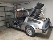
Long time lurker....Finally became a owner again on 10/21, VIN#5791. Slowly making my way through the car and my first question has to do with the ballast resistor. The by-pass relay wires are not connected to anything. In all the pictures I have found online, it looks like the relay wires connect directly to the resistor. Not the case here. Hoping someone can shed some light on why I seem to have so many disconnected wires in this area. Thank you!
Also.....what is the best way to get pictures posted directly into the thread? Seems like I'm making it too difficult on myself.


 Reply With Quote


