FRAMING JOHN DELOREAN - ON VOD
www.framingjohndeloreanfilm.com
-
Member


Originally Posted by
Ron

Red & Black is for a noise suppression capacitor (1uF iirc). Many don't have them.
Getting a spade terminal splitter (AKA Double Male-Female Adapter) is probably your best bet...you'd regret splicing it later.
Thank you!
-
Senior Member

Originally Posted by
AZ-D
Hello all,
Long time lurker....Finally became a owner again on 10/21, VIN#5791. Slowly making my way through the car and my first question has to do with the ballast resistor. The by-pass relay wires are not connected to anything. In all the pictures I have found online, it looks like the relay wires connect directly to the resistor. Not the case here. Hoping someone can shed some light on why I seem to have so many disconnected wires in this area. Thank you!
Also.....what is the best way to get pictures posted directly into the thread? Seems like I'm making it too difficult on myself.

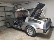
It looks like someone bypassed the relay.
You have a blue and white? Wire in your hand also a green and yellow
you also have a green and yellow on the left side of your balast It looks like the green and yellow wires should be connected to each other and the Blue and white should go to the resistor.
Do not change anything based on what I am saying look at the diagram post in this thread and know for sure.
Just saying thats what it looks like!
 Posting Permissions
- You may not post new threads
- You may not post replies
- You may not post attachments
- You may not edit your posts
-
Forum Rules


 Reply With Quote