I wonder what that black rectangle represents also. I never really gave it much thought. I would have guessed it to indicate a connector but I don't know if that's always true.Originally Posted by Jonathan


Location: Leonardtown, MD
Posts: 9,003
My VIN: 03572
I wonder what that black rectangle represents also. I never really gave it much thought. I would have guessed it to indicate a connector but I don't know if that's always true.

Location: Netherlands
Posts: 612
My VIN: 3695
Club(s): (DCN)
Those black rectangles are all over the schematic, for example near the wing mirror motors:ImageUploadedByTapatalk1405848079.636105.jpg

Location: Las Vegas
Posts: 2,497
My VIN: 6585
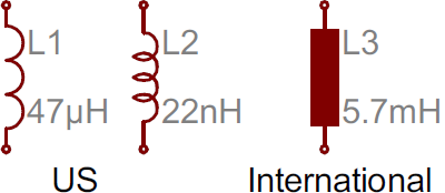
Some quick research shows that apparently there are international Schematic Symbols, and then US Schematic symbols as well. I had no idea, and feel pretty ignorant now. So apparently an empty box is the international symbol for a Resistor, and a filled box as we see here is an Inductor.
https://learn.sparkfun.com/tutorials...-schematic/all
Perhaps these are integrated into the wiring harnesses to block RF noise from electrical motors and other sources from feeding backwards through the electrical system?
Robert
People they come together, people they fall apart...

Location: Illinois
Posts: 2,440
My VIN: 11408
Club(s): (DMWC) (TXDMC) (DCUK) (DOI)
the only inline devices in the car are caps and diodes. No inductors.
I believe those are connections. Like for example where wires pass thru the bulkhead into the engine bay.
Supercharged 5.3L LS4 + Porsche 6spd
[email protected]
lsdelorean.com
I am not affiliated with Delorean Midwest in anyway.
Location: Las Vegas
Posts: 2,497
My VIN: 6585
I think it's a yes and no situation here. Yes, I now believe that my previous assumption was wrong, and that your's that these are connectors is correct. However, they're not bulkhead connectors. Those are separate and not listed. Let me explain.
It looks as though Lotus has had an evolution of sorts when it comes to drafting schematics from the Europa through the Esprit diagrams that I looked at. Absolutely fascinating stuff in terms of Lotus' thought process. The schematic is divided into 3 sections that physically represent the car. Left side of the page represents the front of the car, right side is the rear, center is the passenger cabin. The front and rear bulkheads are the dividing lines. Lotus would make a mark to show *where* the bulkheads would be in relation to the harnesses, and from there you would simply draw down an imaginary, vertical line. That line also represents the division of the harnesses into their 3 main sections. Example.
This leaves us with 3 main sections represented by the harnesses of the same name accordingly: Front | Main | Rear
Within the division of the 3 sections the diagram does NOT show the Connectors on these 3 harnesses where they pass through the bulkheads and connect to one another. It is assumed that there is an understanding that they in fact are there.
Now, *within* those 3 sections, there can be separate sub-harnesses. Ie. an Engine Wiring Harness. Since these harnesses do NOT plug into/pass through the bulkheads, they have separate connectors that are represented by these rectangular boxes. Again, this great insight into Lotus' drafting process and why the Workshop Manual appears as it does: Lotus had their own thought process which they just assumed everyone was already aware of. So, if you have a separate sub-harness/circuit such as the ignition system or the audio system within a certain area, it is completely separate of the Local Harnesses, and its individual connectors are actually portrayed by these black rectangles. Example 2.
So if you compare the Schematic to the mini wiring harness that is hardwired into the back of the window switch, it makes perfect sense!
Again, these are two separate sub-harnesses interconnecting so there is a representation of a connector on the schematic. However for items such as the Frequency Valve, Relay Sockets, Switches, & Diodes, those connectors/sockets only interface with the specific modules/components and not other harnesses, so there is no representation of a connector, as it is assumed the viewer already understands that they are removable.
The confusion is exacerbated with DeLorean because it has 4 main harness sections instead of 3. This is why it's so cluttered and damn confusing.
Lotus Esprit (any other car)
Front | Main | Rear
DeLorean DMC-12
Front | Main Roof | Rear
And to further this, Lotus never having to deal with a 3-Dimentional schematic for a car before chopped up the Roof Harness into several sub-harnesses within the Passenger Cabin.
If you can understand all of that, then you have a greater understanding of the wiring harnesses. If we ever had a community effort to finally clarify the harness, the best thing that we could do would be to highlight the 4 main harness sections with colored bubbles/fields, give the 4 harnesses their own individuals pages, and then refer back to the Workshop Manual's simplistic schematics for the sub-harnesses. In order to show the Bulkhead connectors on the 4 Harnesses, we would need to either completely rearrange the entire schematic, or we'd have to include a new symbol to differentiate these connectors from the others.
Last edited by DMCVegas; 07-21-2014 at 01:07 AM.
Robert
People they come together, people they fall apart...
Location: Netherlands
Posts: 612
My VIN: 3695
Club(s): (DCN)
I for one am very happy with the community work on the schematics so far, like the simplicated schematics, and the full color diagram. It makes life much easier compared to the original diagram, on which it is hard to trace a single line. So: thanks to all people involved.

Location: Fort Lauderdale
Posts: 4,740
My VIN: 02613
Club(s): (DCF)
If you're replacing part of a circuit because one of the wires is damaged, you may find that you need a wire with insulation of a color or color combination that is not available in the U.S.
If you're like me, you may have a good idea in your head of what AWG you want, but that information isn't given on non-U.S. websites. When I was looking up wire from companies outside the U.S., I found myself wondering at the different ways wire size was given. Some had dimensions in cross-section and some in outer diameter, always in mm².
Using information I found on the Internet, I made this chart for my own easy reference, to convert between AWG, cross-section in mm², and diameter in mm². I am posting it here in case it may also come in handy for anyone else.
AWG-Metric-Wire-Size-Chart.pdf
3.0L, automatic, carbureted
Location: Netherlands
Posts: 612
My VIN: 3695
Club(s): (DCN)
On the topic of wiring thicknrss, please note that (at least in Europe) the so called Thin Wall wiring has become standard. As the isolation is a different material, it can be thinner and therefore the wire is more flexible and easier to work with. Please correct me if i'm wrong.. here's the source on the topic: http://www.autosparks.co.uk/index.php?content_page=52 and here: http://www.rdae.nl/draad-en-kabel/en...d-info-pagina/ (dutch)
Last edited by robvanderveer; 11-15-2014 at 05:41 PM.
Location: Leonardtown, MD
Posts: 9,003
My VIN: 03572
Insulation is available in two ratings for the most part. 600 volt or 300 volt. So it's not really the voltage rating for our cars but the thicker insulation can protect the wire more if there is abrasive action.
Some speaker wire I've seen 50 volt rated.
If you can get the circular mill value of the wire that will let you reference it to wire size (AWG). It also lets you know what two wires of one size would equal in another size.
example:
16 AWG has 2580 cmil, so two 16 AWG has 5160 cmil
13 AWG has 5180 cmil so two 16 AWG is better than 14 AWG but less than 12 AWG

Location: Oak Park, CA
Posts: 984
My VIN: 6575
Kind of along the lines of this thread.
Here's the wiring diagram for swapping over from the OEM power mirror switch to the new GM-style switch. It'll take you five minutes with this diagram.
New Power Mirror Switch Wiring.jpg
Alex Abdalla
6575
Late 1981, Grey 5-speed, 75k miles. Built 11/11/81
A stock-look with modern, reliable technology.
A full restoration with step-by-step "what I did" is in progress at www.delorean6575revisited.blogspot.com
 Dave M vin 03572
 Reply With Quote